单励磁和双励磁系统
励磁是指向电动机等机电能量转换装置提供电输入。励磁在电机中产生工作磁场。有些电机需要单电输入,而有些则需要双电输入。
因此,根据机电能量转换系统的电输入数量,可将其分为两种类型 −
单励磁系统
双励磁系统
单励磁系统
顾名思义,单励磁系统仅由一个电激励线圈组成,用于在机器或任何其他机电能量转换装置中产生工作磁场。因此,单励磁系统仅需要一个电输入。
单励磁系统由缠绕在磁芯上的线圈组成,并连接到电压源,从而产生磁场。由于该磁场,由铁磁材料制成的转子(或移动部件)会受到扭矩,该扭矩会将其移向磁场较强的区域,即施加在转子上的扭矩会试图将其定位在磁通路径中显示最小磁阻的位置。磁阻取决于转子角度。该扭矩称为磁阻扭矩或凸极扭矩,因为它是由转子的凸极引起的。
单励磁系统分析
我们做出以下假设来分析单励磁系统 −
对于任何转子位置,磁通量 ($\psi $) 和电流 ($\mathit{i}$) 之间的关系是线性的。
线圈的漏磁通可忽略不计,这意味着所有磁通都流过主磁路。
磁滞损耗和涡流损耗被忽略。
所有电场都被忽略,磁场占主导地位。
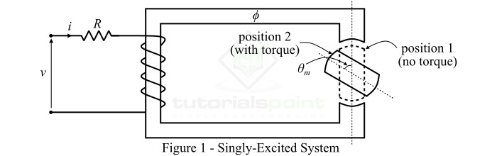
考虑如图 1 所示的单激励系统。如果 R 是线圈电路的电阻,则通过应用 KVL,我们可以将电压方程写为,
$$\mathrm{\mathit{v\:=\:iR\:+\:\frac{\mathit{d\psi }}{\mathit{dt}}}\cdot \cdot \cdot (1)}$$
将方程 (1) 乘以电流 $\mathit{i}$,我们得到,
$$\mathrm{\mathit{vi\:=\:i^{\mathrm{2}}R\:+\mathit{i}\:\frac{\mathit{d\psi }}{\mathit{dt}}}\cdot \cdot \cdot (2)}$$
我们假设系统初始条件为零,并对方程 (2) 两边进行积分到时间,我们得到,
$$\mathrm{\int_{0}^{\mathit{T}}\mathit{vi\:dt}\:=\:\int_{0}^{\mathit{T}}\left ( i^{\mathrm{2}}\mathit{R}\:+\mathit{i}\:\frac{\mathit{d\psi }}{\mathit{dt}} ight )\mathit{dt}}$$
$$\mathrm{\Rightarrow\int_{0}^{\mathit{T}}\mathit{vi\:dt}\:=\:\int_{0}^{\mathit{T}}\mathit{i^{\mathrm{2}}R\:dt}\:+\:\int_{0}^{\psi }\mathit{i\:d\psi }\cdot \cdot \cdot (3)}$$
公式 3 给出了单激励系统输入的总电能,它等于两部分,即
第一部分是电损耗 ($\mathit{W_{el}}$)。
第二部分是有用的电能,它是场能 ($\mathit{W_{f}}$) 和输出机械能 ($\mathit{W_{m}}$) 的总和。
因此,我们可以用符号表示公式 3,
$$\mathrm{\mathit{W_{in}}\:=\:\mathit{W_{el}}\:=\:\left (\mathit{W_{f}} \:+\:\mathit{W_{m}} ight )}\cdot \cdot \cdot (4)$$
单激发系统磁场中存储的能量如下,
$$\mathrm{\mathit{W_{f}}\:=\: \int_{0}^{\psi }\mathit{i\:d\psi }\:=\:\int_{0}^{\psi }\frac{\psi }{\mathit{L}}\mathit{d\psi }\:=\:\frac{\psi ^{\mathrm{2}}}{2\mathit{L}}\cdot \cdot \cdot (5)}$$
对于转子运动,其中转子角度为 $\mathit{ heta _{m}}$,在单激磁系统中产生的电磁转矩由下式给出,
$$\mathrm{\mathit{ au _{e}}\:=\:\frac{\mathit{i^{\mathrm{2}}}}{\mathrm{2}}\frac{\mathit{\partial L}}{\mathit{\partial heta _{m}}}\cdot \cdot \cdot (6)}$$
单励磁系统最常见的例子是感应电动机、PMMC 仪器等。
双励磁系统
具有两个独立线圈以产生磁场的电磁系统称为双励磁系统。因此,双励磁系统需要两个独立的电输入。
双励磁系统分析
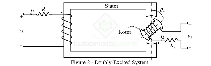
双励磁系统由两个主要部分组成,即定子和转子,如图 2 所示。这里,定子缠绕着电阻为 R1 的线圈,而转子缠绕着电阻为 R2 的线圈。因此,有两个独立的绕组,由两个独立的电压源激励。
为了分析双励磁系统,做出以下假设 −
对于任何转子位置,磁通量 ($\psi$) 和电流之间的关系是线性的。
磁滞和涡流损耗被忽略。
线圈的漏磁可以忽略不计。
电场被忽略,磁场占主导地位。
两个绕组的磁通量由以下公式给出:
$$\mathrm{\psi _{\mathrm{1}}\:=\:\mathit{L_{\mathrm{1}}i_{\mathrm{1}}}\:+\:\mathit{Mi_{\mathrm{2}}}}\cdot \cdot \cdot (7)$$
$$\mathrm{\psi _{\mathrm{2}}\:=\:\mathit{L_{\mathrm{2}}i_{\mathrm{2}}}\:+\:\mathit{Mi_{\mathrm{2}}}}\cdot \cdot \cdot (8)$$
其中,M为两个绕组之间的互感。
应用KVL,我们可以写出两个线圈的瞬时电压方程如,
$$\mathrm{\mathit{v}_{\mathrm{1}}\:=\:\mathit{i_{\mathrm{1}}R_{\mathrm{1}}}\:+\:\frac{\mathit{d\psi _{\mathrm{1}}}}{\mathit{dt}}}\cdot \cdot \cdot (9)$$
$$\mathrm{\mathit{v}_{\mathrm{2}}\:=\:\mathit{i_{\mathrm{2}}R_{\mathrm{2}}}\:+\:\frac{\mathit{d\psi _{\mathrm{2}}}}{\mathit{dt}}}\cdot \cdot \cdot (10)$$
对于双激发系统, 磁场中存储的能量由下式给出:
$$\mathrm{\mathit{W_{f}}\:=\:\frac{1}{2}\mathit{L_{\mathrm{1}}i_{\mathrm{1}}^{\mathrm{2}}}\:+\:\frac{1}{2}\mathit{L_{\mathrm{2}}i_{\mathrm{2}}^{\mathrm{2}}}\:+\:\mathit{Mi_{\mathrm{1}}i_{\mathrm{2}}}\cdot \cdot \cdot (11)}$$
并且,在双激发系统中产生的电磁转矩由下式给出:
$$\mathrm{\mathit{ au _{e}}\:=\:\frac{\mathit{i_{\mathrm{1}}^{\mathrm{2}}}}{\mathrm{2}}\frac{\mathit{dL_{\mathrm{1}}}}{\mathit{d heta _{m}}}\:+\:\frac{\mathit{i_{\mathrm{2}}^{\mathrm{2}}}}{\mathrm{2}}\frac{\mathit{dL_{\mathrm{2}}}}{\mathit{d heta _{m}}}\:+\:\mathit{i_{\mathrm{1}}i_{\mathrm{2}}}\frac{\mathit{dM}}{\mathit{d heta _{m}}}\cdot \cdot \cdot (12)}$$
在公式 12 中,第一个两个项是磁阻转矩,最后一个项给出了由于两个场相互作用而产生的共轴转矩。
双励磁系统的实际例子有同步机、转速表、他励直流机等。